


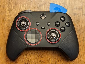
This guide can be used as a prerequisite to repair or replace parts on the Elite Series 2 Controller.
Slightly differing from the previous model, the faceplate needs to be removed before anything else. Begin by removing the joystick caps and d-pad cover.
Once these are removed, you'll need to begin working an opening tool along with the picks around the faceplate starting at the top-left or top right.
Slowly work around the faceplate to loosen the clips using primarily the plastic opening tools to prevent any damage to the faceplate & internal components.
This is the only part in the face removal I would suggest using the metal spudger as you'll need a little more leverage to release the adhesive holding the faceplate down.
Insert the metal spudger in the area located but only as far as you need to get some leverage to pry the faceplate up. Work cautiously and slowly as this can easily damage components.
The adhesive is located in two places and because this doesn't seal the device together for IP-67/68 requirements, it isn't necessary to replace.
The joysticks are screwed onto the stem of the potentiometers and will need some convincing to remove. These will need to be twisted counter-clockwise to remove with either of the following methods:
Method 1: Using a joystick cap - try this first regardless as it has less possibility of damaging the device. Insert one of the joystick caps to each of the joysticks and attempt to twist by hand. If they are too tight, proceed to the second method.
Method 2: Using pliers - using as little force as necessary to prevent slipping, squeeze the joystick near the base, where the bevel allows for a "flat edge" that the pliers can grip. Once these are loose, revert to method 1 to continue the removal.
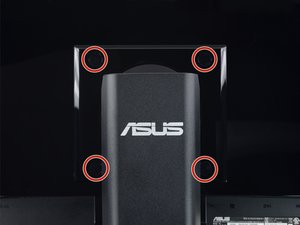
Remove the six T-8 Security screws holding the front and the back of the controller together. Note: one (highlighted green) is covered by a white paste/sticker that crumbles when removed; this lets you know if someone has previously disassembled your device.
Once the screws are removed, you can insert a spudger under a vibration motor to provide a little leverage to separate the front from the back of the device.
The third image shows the front assembly removed from the back cover.
Begin by peeling back the tape (tweezers might help) covering the connection on the green board.
While holding the tape back, insert the plastic pointed spudger under the connections, and the force of pushing the spudger under them should be enough to release them from the board.
The wires will need to be desoldered from the board, and will be replaced later for reassembly.
Note: each pair of wires has the black cable soldered to the lower connection; keep this in mind for the reassembly if the pictures from this guide aren't nearby.
Note: You may be able to get away without desoldering these, depending on what you need to reach (credit to @bikemerlin), but due to the simplicity and fragility of these connections, I would suggest removing them to prevent additional damage.
Some of the solder in this controller requires a very high temperature to release. I had mine set to 450 C, however you may be able to remove it at a lower temperature.
Remove the two T-6 screws from the board near the vibration motors.
Begin removing the motherboard by sliding it up along the pins (as noted in the picture). The left side will need to be lifted off of its pin and the board rotated counter-clockwise at a slight angle before it will be able to slide the remaining distance off of the right (longer) pin.
The triggers will flex up a bit which allows a little extra room for the board. As with everything else in this disassembly, use caution and patience to prevent damage to any of the components.
Once the motherboard has been removed, you may have already noticed the headphone jack has moved or fallen. If it hasn't remove it from the board now.
There are two tabs holding the retainer for the bar in place. Gently pop these toward you with a spudger and they'll slide up from their own tension. Note: the retainer will likely stay attached to the bumper assembly, but must be removed from the main controller assembly before proceeding to the next step.
Once the retainer has been released, again use the spudger to gently pry the buttons outward and upward (in the direction of the arrow in the image) which will release them from another clip. Do this on both sides.
As user Shane Muir has pointed out, please be careful due to the fragility of the retainer in this step. It can easily be broken.
Remove the four T-6 screws holding the daughterboard to the controller frame. Keep in mind this board holds all of the remaining buttons in place, so be careful none of them are lost when removing this.
Note: All of the buttons have clips surrounding them that prevent any of the buttons from being installed in the wrong place; be sure not to force any of them into a different location when reassembling the device.
When reassembling, do not force anything into place as this could indicate something has been installed improperly.
That's it! Hopefully this guide allowed you to access any components that need replacing.
-
 微信公众号
微信公众号