


This disassembly guide is complete enough to replace the shutter mechanism if necessary.
I initiated the disassembly because I thought the shutter assembly was broken, but upon reaching the shutter assembly, found a loose screw on the sensor mount that was causing the problem by jamming in the shutter. I fixed the sensor mount, reassembled the camera, and it works. Saved myself $2000. No way I would have disassembled a camera this expensive if it worked.
I would vote for a pretty high repairability score for this camera. Very little adhesive. The screws are all simple phillips head. I used a lot of random iFixIt tools for the connectors etc.
I marked the disassembly difficult because of the cable manipulation required removing the motherboard especially.
Remove the SD cards and battery.
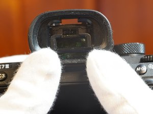
The EVF cover comes off by snapping up, no screws.
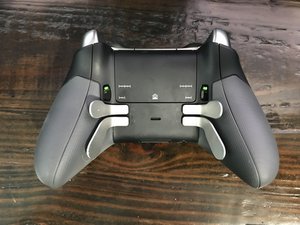
Remove the two bottom metal covers by removing the 8 screws. They are both held on by the same screws.
Remove the electronic view finder screws including the screw that holds the focus knob on.
To remove the focus knob screw, use a spudger to hold the focus knob from spinning while you unscrew.
The rubber hand grip has to be removed to reach screws underneath. Get under one corner, then peel it off slowly.
The screw with the red circle is shorter. Note this for reassembly.
More screws required to get the camera back off in one piece.
Notice the silver screws behind the rubber grip.
Remember the single screw behind the display. Required to remove the camera back.
The back cover requires some prying but not a lot. If it's too difficult, check for screws to remove.
There is just one ribbon cable connecting the entire back to remove when the back is loose. The connector is a ZIF type that flips up toward the top of the camera to loosen.
Notice at this point the ports covers (HDMI/headphone and USB-C/multi) kind of fall off with the back cover so when you put the back cover back on, you will have to replace these ports covers before securing the back cover.
There are 2 connectors to the EVF.
One is ZIF that loosens by flipping down.
The other is standard friction-fitted.
The EVF can be pried out gently.
Also carefully remove the pillow pad behind the EVF. Be careful because it can be brittle.
The 2 connectors are both ZIF and loosen by flipping up toward the top of the camera.
There are 7 total screws holding on the top.
1 screw is under where the camera is labelled a7iii. It is the silver one on the right as opposed to the black one on the left in a similar position.
2 screws are behind where the EVF was, partially hidden by the pad when in place. They are silver even though they look black in the photos.
1 screw is in the top-right facing back under where the exposure adjustment knob is. Silver.
1 screw is in the battery compartment. Black.
2 screws are under where the rubber hand-hold was.
Once the connectors are disconnected and the screws are out, the top comes off pretty easily.
Prepare a small baggie for the headphone jack parts.
Remove the electrical tape protecting the headphone jack. Be careful not to grab the ribbons behind the tape when you remove the tape.
Disconnect the connector. There is just one connector.
Remove the 2 screws holding the headphone jack on.
The anti-static tape has to be removed to access various parts. gently pry it up. Don't cut anything you can't remove yet just get it out of the way.
Battery connector identified by having only two conductors, each very thick. ZIF, loosens by flipping down toward bottom of the camera.
Connector under the processor anti-static tape is friction fit. Steady-shot cable.
2 connectors here are ZIF, loosen by flipping down toward bottom of the camera. Both are imager connectors.
2 connectors under battery connector are friction-fitted. Uper one is the shutter connector. The lower one is the E-mount connector
External mic connector at top left is friction-fitted.
1 connector (under multi-port) on opposite side before flipping the motherboard up is friction-fitted.
On reassembly, I put the motherboard in place with one screw lightly tightened on the side of the board opposite multip-port connector, then used one of the longer screws to hold the motherboard in place but loose for more space while I inserted the multi-port connector.
It worked well. This connector is designed to be inserted with the motherboard in place. There is a cut-out in the motherboard that allows you to push the cable in). MB charge motor connector.
The 5 screws holding on the motherboard are easy to see.
Feed the battery connector through the hole to be able to flip the mother board up toward the top of the camera.
2 connectors on front side of motherboard are friction-fitted.
When reassembling, I initially tried to put these cables on with the motherboard in position to avoid having to feed the battery cable through with these 2 cables connected, but it turned out much easier to connect these cables first with the motherboard flipped up then flip the motherboard into place feeding the battery cable through.
1-wire Wi-Fi antenna connector is friction-fitted. (on reassembly, I connected the WiFi cable first, then the other two front-side cables before flipping the motherboard down into place).
There are 2 sticky cables that hold this block on besides the screws. Carefully remove the cables.
There are 4 screws that hold this block on. The screws are easy to find.
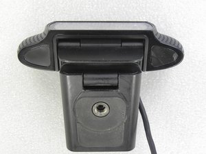
Remove the cover to reveal the steady-shot anti-shake sensor block.
The photo is with the anti-shake unit taken off.
BEFORE YOU TAKE THE ANTI-SHAKE OFF, be prepared to mark the numbers and locations of the shim washers. There are three positions for washers and each spot can have up to 2 washers. Mine had a total of 4 washers. The markings are the thickness in 1/100th mm and on reassembly, they should go back in the same place.
These washers set the flatness of the sensor to the front of the camera / lens.
The anti-shake unit is held on by 3 screws and flex tape.
Of course besides looking for the positions of the shim washers, be careful removing this piece because the sensor is attached to it and will be exposed. Furthermore, the sensor mount is flexible and fragile.
You can see the repaired mounts on my sensor block. The bottom screw had come out and the top mounts broke as a result. The loose bottom screw was also jamming in my shutter unit and made me think the shutter unit was broken.
4 screws secure the shutter unit in place. The cables are already disconnected.
-
 微信公众号
微信公众号